Getting Started with Spiker:bit Block Programming
Overview
In this guide, you’ll learn how to use your Spiker:bit and micro:bit to read muscle (EMG) and heart (ECG/EKG) signals and display them right on your micro:bit!
You’ll need:
- 1x Spiker:bit + 1x micro:bit (inserted into the Spiker:bit front slot)
- 3x BYB Large Muscle Electrodes
- 1x BYB Orange Electrode Cable
- 1x USB Cable
Reading a Muscle Signal (EMG)
The EMG signal measures the electrical activity in your muscles.
The Spiker:bit automatically creates a variable called muscle power signal that stores this information so you can use it in your code.
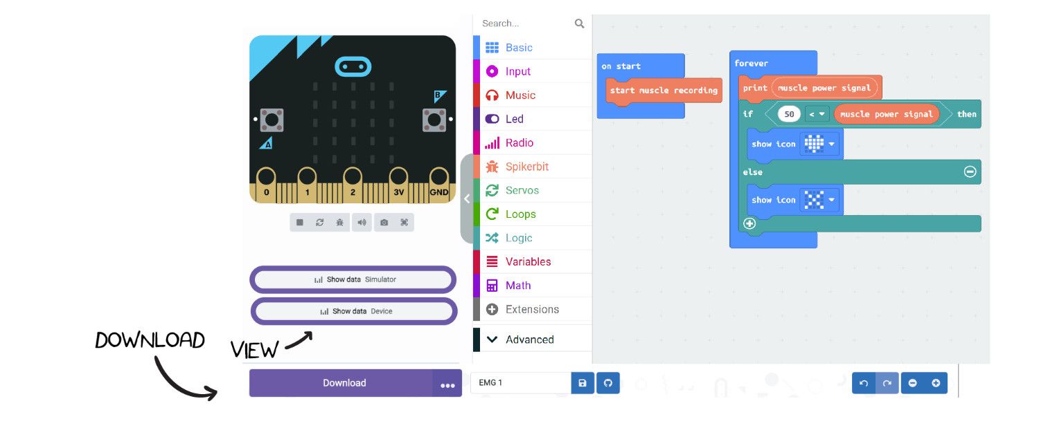
Step 1: Start the Muscle Recording
- Open the MakeCode editor.
- Drag the block “start muscle recording” into the “on start” block.
- This sets up the micro:bit to communicate with the Spiker:bit.
- You only need to do this once per project.
Step 2: Add Some Logic
- From the Logic section, drag an “if else” block.
- Add a “less than” operator inside the condition.
- Compare the
muscle power signalto a small number (like 10)
Note: The muscle activation threshold (default: 10) can be adjusted based on individual reflex strength, electrodes placements, and muscle choice. Use a lower value for weaker signals and a higher one for stronger contractions.
- From Basic, drag two “show icon” blocks:
- Show a heart icon for rest
- Show X icon for flex
Connecting Muscles to Read an EMG Signal
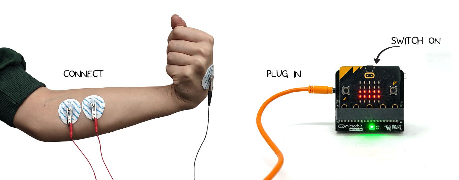
Once your Spiker:Bit is powered and ready, it’s time to connect it to a muscle and see your own electrical activity in action!
Connect two large motor electrodes along a target muscle, the forearm works best for clear, easy-to-control signals. Clip the two red leads to these electrodes, and attach the black ground to an electrode behind your hand to keep the signal clean.
Once the program is loaded, open Show Data to view your EMG signal in real time. Relaxed muscles stay near 0, and a firm flex can rise to around 1000, that’s your muscle’s electrical activity being measured live!
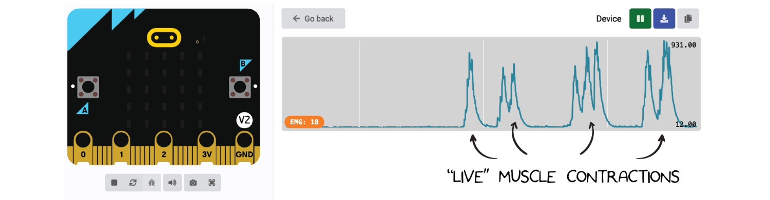
Use this range to adjust your activation threshold (default: 10), set it lower for weaker signals and higher for stronger contractions. Finding the right value helps your readings stay stable and responsive.
Now you can use standard micro:bit code to make your EMG signal do something fun, play a sound, move a motor, or trigger lights whenever you flex. Your body’s electricity becomes your new controller! The possibilities are endless!
Reading a Heart Signal ECG
The Spiker:bit can also record ECG signals. This requires a different electrode placement and a minor modification to the code.
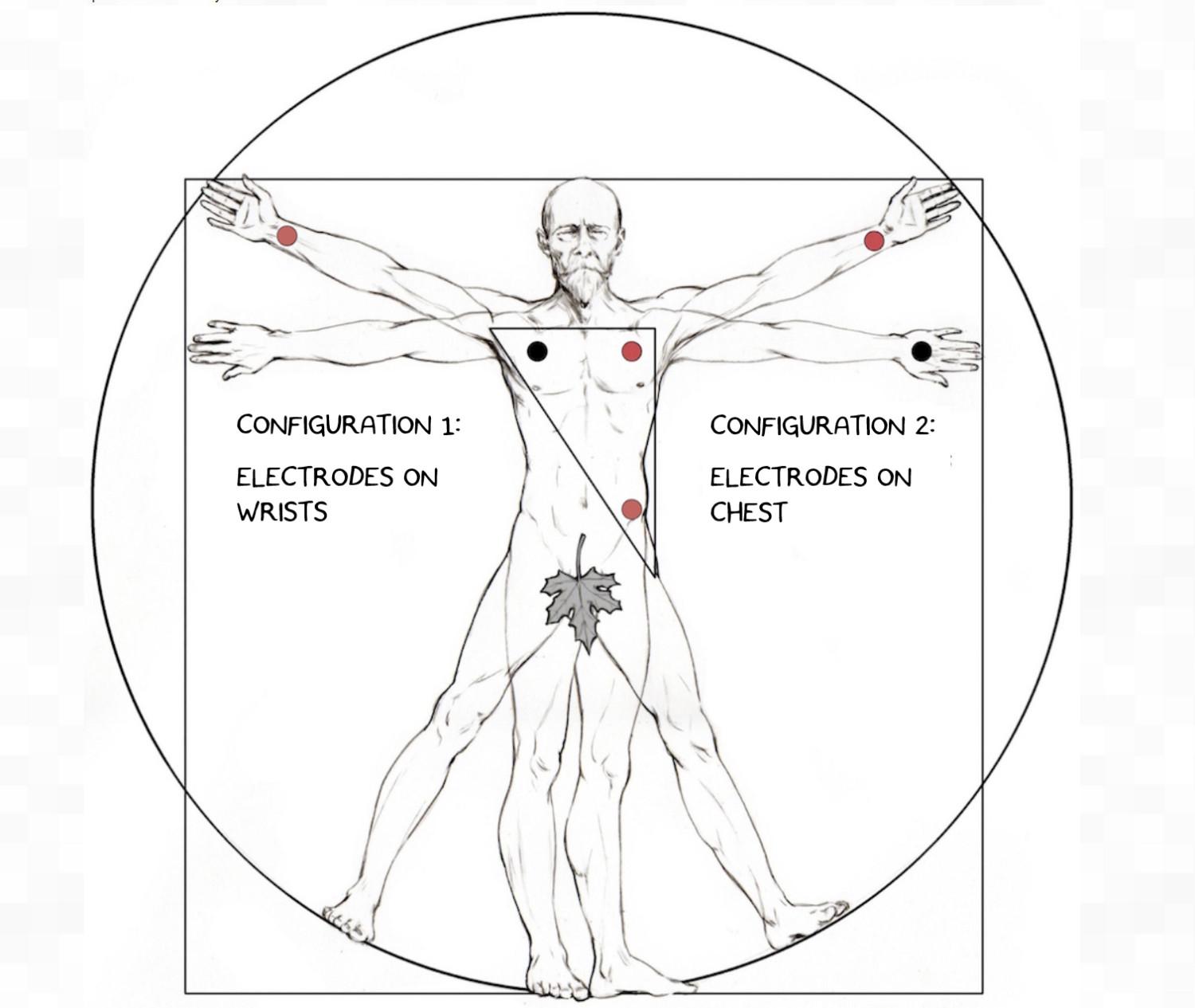
Step 1: Electrode Placement for ECG
A common placement for a simple ECG reading (based on Einthoven's triangle) is:
- Ground (Black Clip): Back of the left hand or wrist.
- Positive (Red Clip): Inside of the right wrist or forearm.
- Negative (Other Red Clip): Inside of the left wrist or forearm.
Step 2: Update the Code
- Return to your MakeCode project.
- In the on start block, replace start muscle recording with the
start heart recording(ECG) block. - In the forever loop, replace the muscle power signal variable with the heartbeat signal (ECG) variable.
- Download this new program to your micro:bit.
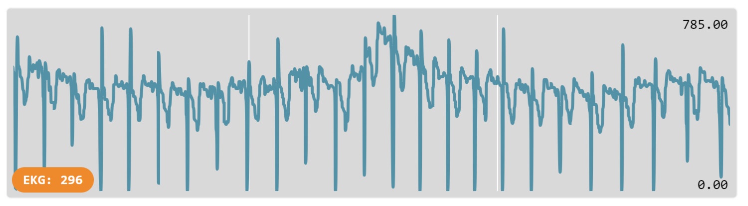
Open the "Show Data (Device)" graph. With the electrodes properly placed, you should now see a regular, rhythmic spike corresponding to your heartbeat.
Here's what the signal will look like once you're successful:
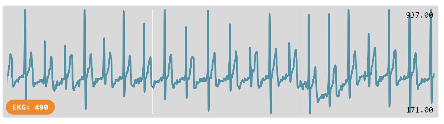
Troubleshooting Note: If the spikes appear inverted (pointing down), the signal polarity is reversed.
To fix this, swap the two red alligator clips on your wrists.
Using Text-Based Editors in MakeCode
The MakeCode editor supports both visual and text-based programming. You can seamlessly toggle between Blocks, JavaScript, and Python using the tabs at the top of the editor. To learn more about transitioning to syntax-based coding, read about text-based programming here.